Choosing the right Isolation Transformer is a practical engineering decision, not a simple catalog exercise. It affects electrical safety, equipment uptime, signal integrity, and maintenance costs. In hospitals, laboratories, factories, and data centers, a transformer must handle real operating conditions, including inrush current, nonlinear loads, heat, vibration, and limited installation space. Small errors matter.
The International Energy Agency reported that data centers consumed approximately 240–340 TWh of electricity globally in 2022. Its Electricity 2024 report projects demand could reach 620–1,050 TWh by 2026. This growth increases pressure on power quality and electrical resilience. An Isolation Transformer can help separate sensitive loads from upstream disturbances, but it cannot correct every voltage or grounding problem. The selection must consider voltage ratio, rated capacity, frequency, impedance, shielding, insulation class, and expected harmonic content. Noise matters. So does heat.
Safety and performance should be verified against recognized guidance, including IEC 61558, IEEE 1100, and applicable national electrical codes. Manufacturers should provide temperature-rise data, short-circuit withstand ratings, efficiency figures, acoustic levels, and routine test documentation. Independent certifications also improve confidence, although certification alone does not guarantee a suitable design. That assumption needs challenging. A technically compliant transformer may still fail under repeated motor starts or poorly balanced loads. This guide explains how to compare specifications, estimate actual demand, identify hidden installation risks, and select a dependable Isolation Transformer for the application rather than relying on price or nameplate capacity.
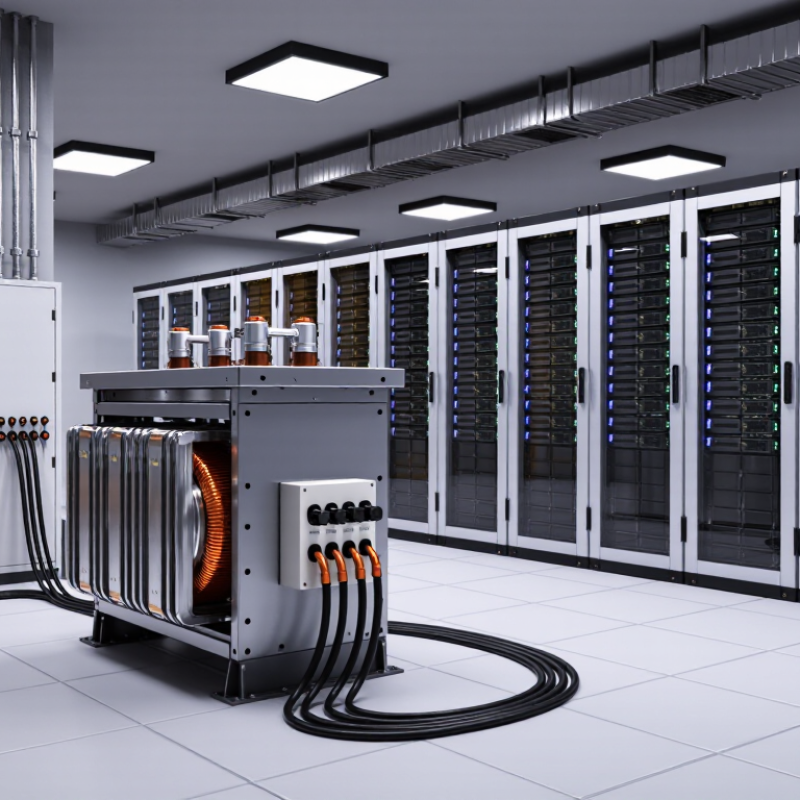
An isolation transformer separates the input circuit from the output circuit through magnetic coupling. Its windings share energy, but they do not share a direct electrical path. This separation is called galvanic isolation. It can reduce shock hazards, interrupt unwanted ground paths, and limit common-mode noise. The transformer does not automatically make every installation safe.
Core function matters more than appearance. A one-to-one turns ratio usually maintains a similar voltage level. Other ratios can raise or reduce voltage. Check the required input voltage, output voltage, frequency, and load power before choosing one. Motors, switching supplies, and control systems may create high starting currents. A transformer sized only for normal running power can overheat or trip protection. That mistake is common.
Physical details deserve attention. Look for insulation ratings, dielectric test results, temperature limits, shielding, and suitable enclosure protection.
A shield between windings may reduce capacitive noise, but it needs correct grounding. In practical panel inspections, loose terminals and poor ventilation often cause more trouble than the transformer itself.
I would also verify the waveform, because some units perform poorly with distorted power. No choice is perfect. The application may change after installation, so measurements under real load remain valuable.

An isolation transformer should begin with electrical requirements, not catalogue size. Record input voltage, output voltage, frequency, phase, load type, and required kVA. Motors, drives, and medical equipment can create high inrush currents. A transformer that matches steady load may still trip during startup. I have seen this mistake cause repeated nuisance shutdowns. It is easy to overlook.
Safety requirements deserve equal attention. IEC 61558-1 addresses transformer safety, insulation, temperature rise, and protection against electric shock. OSHA 1910.333 also requires guarding or other controls for exposed energized parts above 50 volts. Specify the grounding method, shielding needs, enclosure rating, and acceptable leakage current. NFPA reported about 32,000 U.S. home fires involving electrical distribution and lighting equipment annually from 2015 to 2019. The figure is not an industrial transformer statistic, but it shows why protection details cannot be treated as paperwork.
Equipment protection adds another layer. Check short-circuit withstand, overcurrent coordination, surge exposure, and harmonic heating. The U.S. Department of Energy has estimated that distribution transformers consume roughly 2.5% of national electricity use. Efficiency therefore affects operating cost, not only purchase price. Ask for tested efficiency, temperature-rise data, sound levels, and fault protection settings. Smaller is not always better. Oversizing can increase idle losses, while undersizing can damage insulation. The selection process remains imperfect when future loads are uncertain, so document every assumption and review it with a qualified electrical engineer.
How to Choose the Right Isolation Transformer?
Matching transformer ratings to voltage, load, and application starts with the nameplate. Confirm the source voltage, secondary voltage, frequency, phase, and grounding arrangement. A 480-to-120 V transformer may look suitable, but control circuits can still fail if frequency or bonding is incorrect. Check both normal voltage and permitted variation.
Size capacity from the real load, not the hoped-for load. For single-phase systems, calculate kVA as volts multiplied by amps, divided by 1,000. Three-phase systems require the 1.732 factor. Add practical thermal headroom for motors, relays, and future equipment. Inrush current matters. It can trip upstream protection even when running current seems modest. A common field mistake is ignoring it.
Application changes the rating. Sensitive instruments may need electrostatic shielding and low leakage current. Variable-speed drives can create harmonics and extra heating. Outdoor or dusty locations require suitable enclosures and temperature ratings. The Lawrence Berkeley National Laboratory and U.S. Department of Energy reported that American data centers used about 176 TWh in 2023, potentially reaching 325–580 TWh by 2028. That growth makes realistic load planning less optional. IEA’s Electricity 2024 report also projected strong global electricity-demand growth through 2026. Reports are useful, but local measurements remain better. A spreadsheet can still miss reality. Review peak demand, duty cycle, ambient temperature, and fault protection before approving the transformer.
| Selection Dimension | Typical Requirement or Range | How to Match the Transformer | Practical Example | Important Check |
|---|---|---|---|---|
| Primary Voltage | The available supply voltage, such as 120 V, 208 V, 230 V, 400 V, or 480 V AC. | Select a primary winding rated for the actual measured or specified supply voltage. If the supply varies, consider an input tap range. | A 480 V supply requires a transformer with a 480 V primary rating or an approved 480 V tap. | Do not connect a transformer to a higher voltage than its winding rating. |
| Secondary Voltage | The voltage required by the load, commonly 12 V, 24 V, 120 V, 208 V, or 230 V AC. | Choose the secondary voltage based on the equipment nameplate and allowable operating range, not only the nominal voltage. | A 230 V control load supplied from 400 V may use a 400-to-230 V isolation transformer. | Verify whether the load needs a center tap, neutral reference, or a floating output. |
| Power Rating | Rated in VA or kVA. Common sizes include 100 VA, 500 VA, 1 kVA, 5 kVA, and 10 kVA. | Select a rating at least equal to the calculated continuous load, with additional capacity for starting and future expansion. | A 750 VA continuous load should generally use a transformer rated above 750 VA, such as 1 kVA, after checking inrush. | Do not use the transformer continuously at its limit unless the manufacturer specifically permits it. |
| Load Current | Single-phase apparent power: VA = V × A. Three-phase apparent power: VA = √3 × V × A. | Calculate current at the secondary voltage and compare it with the transformer's rated secondary current. | A 120 V, 5 A single-phase load requires approximately 600 VA before applying a design margin. | Include all simultaneously operating loads, not only the largest individual device. |
| Continuous and Intermittent Load | Continuous loads operate for extended periods; intermittent loads cycle on and off. | Size for the expected continuous duty and confirm the thermal performance for the actual duty cycle. | A 400 VA motor-control load with frequent starts may need more capacity than a 400 VA resistive load. | Duty cycle, enclosure temperature, and ventilation affect usable capacity. |
| Inrush and Starting Current | Motors, solenoids, contactors, capacitive power supplies, and some electronic equipment draw temporary starting current. | Use the manufacturer's inrush data or select a transformer with sufficient short-term overload capability. | A contactor coil may have a much higher pickup VA than its sealed VA. | Check that the upstream breaker will not trip during energization or load starting. |
| Phase Configuration | Single-phase or three-phase, according to the source and load. | Use a single-phase unit for single-phase loads and a three-phase unit where phase balance and three-phase operation are required. | A three-phase motor system normally requires a three-phase transformer with the appropriate winding connection. | Confirm delta or wye connections, neutral availability, and phase sequence requirements. |
| Frequency | Usually 50 Hz or 60 Hz. | Select a transformer designed for the supply frequency. A 60 Hz-only unit should not automatically be used on 50 Hz service. | A transformer specified for 50/60 Hz is suitable for either frequency within its rated voltage limits. | Incorrect frequency can increase core flux, heating, noise, or saturation risk. |
| Voltage Regulation | The secondary voltage changes as the load changes; lower regulation generally means better voltage stability. | Choose low regulation for sensitive controls, instrumentation, and equipment with narrow voltage tolerances. | A control system requiring stable 24 V AC may need better regulation than a simple resistive heater. | Check the secondary voltage at both no-load and full-load conditions. |
| Isolation and Shielding | Galvanic separation between primary and secondary; optional electrostatic shield for noise reduction. | Use a shielded isolation transformer where common-mode electrical noise or sensitive measurement circuits are concerns. | Instrumentation and communication equipment may benefit from a grounded electrostatic shield. | A shield reduces capacitive noise coupling but does not replace correct grounding, filtering, or surge protection. |
| Insulation Class and Temperature Rise | Common insulation systems include Class B, Class F, and Class H; temperature rise may be specified as 80 °C, 115 °C, or 150 °C. | Choose an insulation system and temperature rise suitable for the ambient temperature and expected service life. | A hot industrial enclosure may require a lower temperature-rise design or additional cooling. | Higher ambient temperature reduces the available thermal margin. |
| Installation Environment | Indoor, outdoor, dusty, damp, corrosive, hazardous, or washdown environments. | Select an enclosure and mounting method with an appropriate ingress protection level and environmental rating. | A clean indoor control cabinet may use a ventilated enclosure, while a wet location needs a suitably protected enclosure. | Enclosure requirements depend on location, ventilation, moisture, dust, and local electrical codes. |
| Protection and Accessories | Primary and secondary fuses or circuit breakers, thermal protection, terminals, taps, and mounting hardware. | Provide protection sized according to transformer full-load current, inrush, conductor ampacity, and applicable code. | A 1 kVA, 240 V primary has a full-load primary current of approximately 4.17 A before considering efficiency and power factor. | Protection must be coordinated so normal energization does not cause nuisance tripping. |
| Safety and Compliance | Applicable electrical, installation, insulation, fire, and workplace safety requirements. | Use a transformer evaluated or certified for the intended region and application, and install it according to local regulations. | Industrial control panels may require documented dielectric withstand, grounding, and enclosure provisions. | Verify the required standard with the qualified designer, inspector, or authority having jurisdiction. |
| Noise and Acoustic Performance | Transformer hum is affected by core flux, mechanical construction, mounting, and load conditions. | Choose a low-noise design and use vibration-isolating mounting where the transformer is near offices, laboratories, or medical areas. | A laboratory installation may require lower acoustic noise than a remote electrical room. | Keep the transformer away from vibration-sensitive equipment and provide adequate ventilation clearance. |
Choosing an isolation transformer starts with the load, not the product label. A single-phase unit suits many control panels and laboratory circuits. Three-phase models fit industrial motors and balanced production equipment. Toroidal designs can reduce audible hum, but they may produce high inrush current. Shielded transformers help limit electrical noise between primary and secondary windings. I have seen oversized units waste space while offering little practical benefit.
Check the required voltage ratio, VA rating, insulation class, efficiency, and temperature rise. Leave capacity for starting current and future equipment. Thermal protection can reduce damage during overloads, while clear terminals simplify inspection. Voltage regulation also matters when sensitive instruments share the circuit. Bigger is not always safer. Sometimes, it only becomes heavier and harder to cool.
Installation conditions can change the decision completely. Mount the transformer in a dry, clean, ventilated location with enough clearance for heat dissipation. Avoid placing it beside strong heat sources or areas with conductive dust. Confirm the enclosure rating for moisture and impact exposure. A qualified electrician should verify grounding, bonding, upstream protection, and local electrical requirements. Keep cable runs short when voltage drop matters. I still recheck the neutral arrangement and measured output after energizing; assumptions can fail quietly. A neat installation is useful, but measured performance is more reliable.
A reliable isolation transformer is chosen beyond its nameplate. Compliance should be checked before installation, not after an inspection fails. Ask for applicable test reports, insulation class, efficiency data, and protective-device requirements. Confirm that the unit matches local electrical codes and the site’s grounding design. Documents matter. Yet paperwork alone cannot prove safe operation.
During commissioning, record input and output voltage, load current, temperature, and unusual hum. A thermal scan can reveal loose terminals before they become expensive faults. Maintenance usually includes cleaning vents, tightening connections, checking insulation, and reviewing alarm history. The schedule should reflect dust, humidity, vibration, and actual loading. A lightly loaded unit in a clean room needs different attention than one near machinery. This detail is often missed. Keep dated records.
Long-term performance depends on heat control and stable insulation. Oversizing may reduce stress, but it can increase cost and idle losses. Undersizing is worse. It may cause overheating during daily peaks and shorten service life. Do not trust a quiet transformer as proof of health. Noise can change slowly, while insulation damage remains hidden. I would also challenge optimistic service-life estimates; site conditions rarely stay perfect. Review trends every year, and replace worn accessories before failure disrupts critical equipment.
Get in Touch
570 Alden Road Unit #10, Markham Ontario Canada, L3R 8N5
Quick Links
Featured Products
Industries