Choosing the right pneumatic solenoid valve is more than matching a pipe size to a catalog drawing. The valve controls compressed air, machine timing, and sometimes the safety of an entire production line. A poor selection may cause slow cylinders, repeated coil failures, air leakage, or unexpected downtime. Small details matter. A dusty workshop and a clean assembly room need different protection levels. A valve used beside a hot press also needs different seals from one installed inside a cool cabinet.
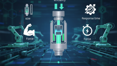
Start with the medium. Clean, dry air is ideal, but real systems often contain moisture, oil, or particles. Check the working pressure, required flow rate, port size, response time, and available voltage. Confirm whether the application needs normally closed, normally open, or double-solenoid operation. Seal materials must match the air quality, temperature, and surrounding chemicals. The correct pneumatic solenoid valve should also fit the control system, mounting space, and maintenance plan.
Field experience shows that oversized valves are not always better. They can increase cost and reduce control precision. A smaller valve may restrict airflow and extend cylinder movement. The datasheet is essential, but it is not the whole answer. Installation position, tubing length, pressure drops, and electrical connections can change actual performance. Test the valve under realistic conditions before full deployment. A neat selection rule can still mislead. Review manufacturer specifications, applicable technical standards, and advice from qualified pneumatic engineers. Reliable choices come from evidence, careful measurement, and a willingness to question initial assumptions.
How to Choose the Right Pneumatic Solenoid Valve?
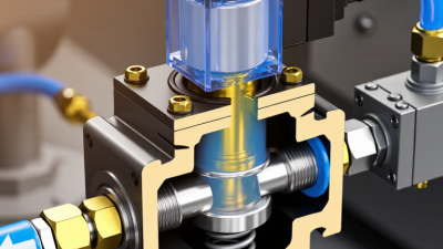
A pneumatic solenoid valve converts an electrical signal into controlled airflow. It directs compressed air to extend, retract, or stop a pneumatic actuator. Inside, an energized coil creates a magnetic field and moves a plunger or spool. This action opens one port while closing another. When power stops, a spring usually returns the valve to its normal position.
That coil is small. Its role is critical. Direct-acting valves move the sealing element directly and suit low flow or low pressure. Pilot-operated valves use air pressure to shift a larger spool. They provide higher flow with lower electrical demand, but need minimum pressure. A practical selection starts with function: 2/2 valves control simple on-off flow, while 3/2 and 5/2 valves manage single-acting or double-acting cylinders.
Efficiency deserves attention. The U.S. Department of Energy’s Improving Compressed Air System Performance sourcebook reports that compressed air may consume about 10% of industrial electricity. Its guidance also identifies leakage losses of 20–30% in poorly maintained systems. The IEA’s Energy Efficiency 2023 report places industry near 37% of global final energy demand. These figures make pressure drop and coil power relevant selection factors.
Check voltage, port size, operating pressure, flow rating, response time, seal compatibility, and ambient temperature. Confirm the fail position during power loss. A valve that is technically suitable may still waste energy through excessive pressure drop. I would also question catalogue flow values, because test conditions can differ from the real machine. Field verification is imperfect, but it often prevents expensive troubleshooting later.
Choosing the right pneumatic solenoid valve starts with operating numbers, not the catalog photograph. Pressure, flow, and port requirements must agree at the same working point. A 1/4-inch port is not automatically suitable. Port size alone misleads.
The U.S. Department of Energy’s Improving Compressed Air System Performance sourcebook reports that compressed air systems can account for 10–30% of industrial electricity use.
Efficient valve selection therefore affects operating cost.
Start with cylinder demand and required cycle speed. Calculate required flow in standardized liters per minute or SCFM. A 63-millimeter bore cylinder moving at 300 millimeters per second displaces about 56 liters per minute at atmospheric reference, before losses.
Then compare valve flow ratings under matching conditions. ISO 6358-1 defines pneumatic flow through sonic conductance and critical pressure ratio. Use ratings tested at comparable inlet pressure, outlet pressure, and temperature. A valve rated at 6 bar may perform differently at 4 bar.
I have seen port diameter used as a shortcut. It saves time, but can create sluggish cylinders.
Pressure range deserves equal attention. Confirm minimum pilot pressure, maximum supply pressure, and allowable pressure drop. For high-cycle equipment, calculate flow during the worst simultaneous movement.
Then check thread standard, seal material, response time, and exhaust arrangement. Dust and moisture matter too.
A clean specification sheet still cannot replace testing on the actual machine. That step is often skipped.
Choosing a pneumatic solenoid valve starts with the actuator, not the valve catalogue.
A single-acting cylinder usually needs a 3/2 configuration with spring return. A double-acting cylinder generally requires a 5/2 valve. For mid-position holding, a 5/3 valve may provide better control, but its center function must match the application.
Check the required electrical control method carefully. A single-solenoid valve changes state when energized and returns when power is removed. This design can be safer during a power failure. A double-solenoid valve keeps its last position, so the control system must manage both coils correctly.
I have seen machines fail because the selected coil voltage did not match the output module. Confirm the voltage, current, connector type, and allowable tolerance before installation.
Use direct control for small, simple circuits. Use a PLC output when timing, interlocking, or fault monitoring matters. DC control is common in automated equipment, while AC control may suit older installations.
The coil’s protection rating also matters near water, dust, or cleaning areas. Check the enclosure rating and cable entry details.
Do not judge performance from port size alone. Air flow, operating pressure, response time, and exhaust capacity affect cylinder movement. A valve can fit physically but still move too slowly.
One practical mistake is selecting a valve before measuring the actual cycle time. Test the complete circuit under real load, because catalogue figures rarely show every installation problem.
How to Choose the Right Pneumatic Solenoid Valve?
Choosing a pneumatic solenoid valve starts with the working medium. Clean, dry air usually permits standard sealing materials. Moisture, oil, chemicals, or abrasive particles require stronger compatibility checks. Review the valve body, seals, and spring materials together. One weak component can shorten service life. I have seen valves fail early because the seal was selected for pressure, not chemical exposure.
The environment matters just as much. Measure operating pressure, temperature, flow rate, and switching frequency. A dusty workshop may need better enclosure protection than a clean assembly area. Outdoor equipment can face rain, condensation, and sudden temperature changes. Check the coil voltage carefully. A mismatch creates unreliable operation or overheating. Avoid choosing by port size alone. Flow capacity and response time may be more important. My first selection once matched the pipe diameter, but the machine still moved too slowly.
Installation details often decide whether a good valve performs well. Keep air lines short and support heavy tubing near the connection. Follow the specified mounting position. Prevent dirt from entering open ports during assembly. Add filtration and drainage when the air supply is inconsistent. Leave enough space to replace the coil and inspect fittings. During commissioning, check for leaks with approved methods and verify several operating cycles. Maintenance records should include pressure readings, switching behavior, and seal condition. Small changes can reveal wear early. Still, inspection intervals should reflect real usage, not only a standard schedule.
| Evaluation Dimension | Selection Factor | Typical Requirement or Condition | Recommended Valve Characteristics | Potential Risk if Mismatched |
|---|---|---|---|---|
| Materials | Valve body | Dry indoor air with limited exposure to moisture or chemicals | Anodized aluminum or engineering-plastic body for low weight and general-purpose service | Corrosion, cracking, or premature leakage |
| Valve body in wet or corrosive areas | Frequent washdown, condensation, salt exposure, or chemical vapors | Stainless-steel construction with suitable surface protection and sealing materials | Rust, pitting, blocked ports, and shortened service life | |
| Seals and diaphragms | Air containing oil mist, elevated temperature, or contact with process fluids | Select seal elastomers according to media, temperature, and lubricant compatibility; common options include NBR, EPDM, and FKM | Swelling, hardening, embrittlement, or internal leakage | |
| Internal wetted parts | High cycling frequency or air with fine particles | Wear-resistant materials, clean internal passages, and filtration upstream of the valve | Spool sticking, increased response time, and unstable flow control | |
| Environment | Ambient temperature | Normal industrial surroundings or temperature near the upper or lower limit of the application | Verify the manufacturer’s rated ambient and medium-temperature range; account for heat from nearby equipment | Coil overheating, seal failure, sluggish operation, or freezing |
| Dust and water exposure | Dusty production area, splash zone, or outdoor installation | Choose a coil enclosure with an appropriate IP rating, protected cable entry, and a housing suited to the installation location | Electrical short circuits, corrosion, and unreliable switching | |
| Hazardous atmosphere | Flammable gas, vapor, or combustible dust may be present | Use equipment with the required hazardous-area certification and installation method; consult applicable local regulations | Ignition hazard, regulatory non-compliance, and serious safety risk | |
| Vibration and noise | Machinery with repeated impact, vibration, or strict acoustic requirements | Use secure mounting, vibration-resistant electrical connections, and a low-noise design when required | Loose connections, intermittent actuation, and accelerated mechanical wear | |
| Installation | Port size and flow capacity | Required actuator speed and air consumption are known | Match the connection size and compare the valve’s flow coefficient or rated flow with the application demand | Slow cylinder movement, pressure loss, or unnecessary air consumption |
| Operating pressure | Supply pressure may vary during production | Confirm minimum and maximum operating pressure, pressure differential, and whether the valve is direct-acting or pilot-operated | Failure to shift, unstable operation, or inability to hold the commanded position | |
| Electrical compatibility | Control system voltage and switching method must match the solenoid coil | Check coil voltage type, rated voltage, power consumption, connector style, and surge-suppression requirements | Coil burnout, control faults, or failure to actuate | |
| Piping and orientation | Valve will be installed in a manifold or connected with flexible tubing | Follow port markings, observe the permitted mounting orientation, support tubing, and avoid excessive tightening torque | Leaks, damaged threads, restricted flow, or incorrect actuator movement | |
| Air preparation | Compressed air contains water, particles, or excess oil | Install filtration and drainage appropriate to the system; use a regulator and lubricator only when permitted by the valve and actuator requirements | Contamination, sticking, seal damage, and reduced operating reliability | |
| Maintenance | Inspection access | Valve is installed in a compact cabinet or difficult-to-reach location | Provide access to the coil, connectors, tubing, filter, and manual override for inspection and replacement | Longer downtime and more difficult troubleshooting |
| Spare parts and serviceability | The system is safety-critical or operates continuously | Prefer replaceable coils and seals, documented part numbers, and a practical repair or replacement procedure | Extended production interruption and higher maintenance cost | |
| Leak testing | Energy efficiency and actuator performance must be maintained | Inspect fittings and tubing regularly; use approved leak-detection methods and repair leaks promptly | Wasted compressed air, pressure loss, and inconsistent motion | |
| Replacement interval | High switching frequency, contaminated air, or demanding duty cycle | Use the rated cycle life as a planning reference and base preventive maintenance on actual cycle count and operating conditions | Unexpected failure and unplanned equipment downtime |
How to Choose the Right Pneumatic Solenoid Valve?
Reliability starts with the working environment, not the catalogue price. Check pressure, temperature, cycle frequency, media quality, and response time. A valve near a dusty press needs stronger sealing and easier cleaning. The U.S. Department of Energy estimates compressed-air leaks can waste 20–30% of compressor output. Poor valve selection can add to that loss. However, field results vary with maintenance and pipe design. Do not treat one percentage as universal.
Safety features deserve equal attention. Choose manual override protection, clear flow markings, suitable voltage control, and fail-safe operation. ISO 4414 provides guidance for pneumatic system safety, including stored-energy control and emergency isolation. In practice, technicians should test the valve after shutdown, not only during installation. A quiet coil is not proof of safe performance. That assumption can be costly.
Tips: Compare total ownership cost, including coils, seals, air consumption, downtime, and labor. Ask suppliers for tested cycle-life data, pressure-drop curves, certificates, spare-part availability, and response times. Supplier support matters during a 2 a.m. stoppage. A technically strong valve becomes less useful when replacement advice arrives days late. Request a sample or pilot installation when conditions are uncertain. My own preference is cautious: pay slightly more for verified data, but challenge every unsupported claim.
Recommended evaluation priorities for reliability, safety, cost, and supplier support
Get in Touch
570 Alden Road Unit #10, Markham Ontario Canada, L3R 8N5
Quick Links
Featured Products
Industries